FUEL SYSTEM.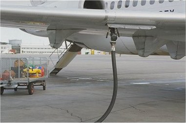 The MD81/82/87 have one center tank and a left and right main tank. All
tanks are an integrated part of the wing. MD83 is also equipped with one
forward and one aft auxiliary tank. Fueling is normally performed from a
station located about midspan on the leading edge of the right wing. If
AC power is available, fueling is normally accomplished by setting the tank
switches on the fueling control panel to desired position. Fuel level float
switches in each tank will automatically close the respective fill valve when
the tank reaches the desired level or becomes full. It is also possible to
perform overwing (gravity) fueling of the main tanks through an adapter in
each tank.
The MD81/82/87 have one center tank and a left and right main tank. All
tanks are an integrated part of the wing. MD83 is also equipped with one
forward and one aft auxiliary tank. Fueling is normally performed from a
station located about midspan on the leading edge of the right wing. If
AC power is available, fueling is normally accomplished by setting the tank
switches on the fueling control panel to desired position. Fuel level float
switches in each tank will automatically close the respective fill valve when
the tank reaches the desired level or becomes full. It is also possible to
perform overwing (gravity) fueling of the main tanks through an adapter in
each tank.
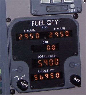 Fuel quantity sensing probes are located in all fuel tanks. The actual amount of fuel in each main and center tank, as well as total fuel capacity and gross weight, are presented on the FUEL QTY display on the center instrument panel. The TEST button is used to test the readout (1 500 in each tank and 4 500 total) as well as to select channel A or B. The ZFW button is used to insert actual ZERO FUEL WIEGHT. Max usable tank capacity 4 200 kg in each main tank and 9 340 kg in center at 0.803 kg/l in spec weight. For the MD-83 only; Forward/Aft auxiliary 1 720 kg. Total 17 740 kg for MD-81/82/87 and 26 385 kg for MD-83. 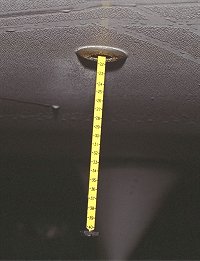 Fuel quantity can also be measured by using the fuelsticks in the bottom of each tank. There are 4 sticks in each main tank and one in the center tank. This is one of the right main tank fuelsticks. There is some frost on the under side of the wing, which is normal. 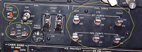 Each fuel tank has two AC boost pumps installed. The LEFT and RIGHT main boost
pumps are connected in parallel while the CENTER tank boost pumps are connected
in series. This ensures that center tank fuel is used first even if the main tank
boost pumps are operating. The center tank fuel will always be transferred to
the main tanks. During normal operation, the left main tank supplies the left engine
and the right main tank supplies the right engine.
Each fuel tank has two AC boost pumps installed. The LEFT and RIGHT main boost
pumps are connected in parallel while the CENTER tank boost pumps are connected
in series. This ensures that center tank fuel is used first even if the main tank
boost pumps are operating. The center tank fuel will always be transferred to
the main tanks. During normal operation, the left main tank supplies the left engine
and the right main tank supplies the right engine.The left and right main tank-to-engine feed lines are interconnected by a crossfeed line via a manually controlled crossfeed valve. This permits both engines to be fed from the same main tank. The crossfeed handle is placed on the forward pedestal. A DC powered START PUMP is installed in the right main tank to provide fuel pressure for start of the APU or an engine if AC power is not available. The air/fuel heater prevents or removes ice accumulation at the fuel filter. Hot air is supplied from the engine 13th compressor stage to a heat exchanger. The bleed air shut off valve is controlled by the FUEL HEAT switch and timer. Later aircraft (from No. 54 and onwards) are equipped with an Alternate Fuel Burn System. In these aircraft the center tank pump switches have three positions, AUTO-OFF-ON. With the switch in AUTO fuel from the center tank will be fed to the engines until the fuel level in the center tank reaches around 5 000 kg. At this level the pumps will stop until the level in the main tanks reaches around 1 800 kg. Then the pumps will start again. The reason for this system is to get the cold fuel away from contact with the upper wing surface in order to minimize the ice formation during ground stop. 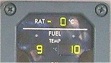 FUEL TEMP can be read from the upper part of the system panel. 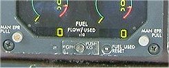 FUEL FLOW and FUEL USED can be read from the lower part of the engine panel. Normally Fuel Flow is indicated kg/hour. By pressing the push button in the middle, the readout displays Fuel Used in kg x 10 for 10 seconds. There is also a FUEL USED RESET button. |