Back to Left pilot instrument/
Right pilot instrument/
Aft pedestal
VSI/TCAS and ATC-transponder.
CONTROL UNIT.
This is a combination of ATC MODE-S transponder and TCAS control.
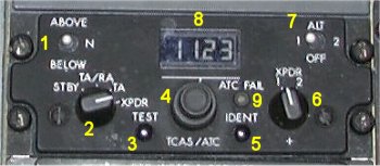
- 1. TCAS vertical scan selector.
- ABOVE - Expands the vertical scan to 9900 ft above and 2700 ft below
the aircraft.
N - Normal position. TCAS vertical scan is +/- 2700 ft.
BELOW - Expands the vertical scan to 2700 ft above and 9900 ft below
the aircraft.
- 2. Function selector.
- STBY - Both ATC interrogators are powered but cannot transmit.
TA/RA - This is the normal operating TCAS mode. In this mode, Traffic and
Resolution Advisories are enabled.
TA - Only TA (TRAFFIC ALERT) is displayed; no RA. This mode prevents
TCAS from issuing RA when intentionally flying close to other aircraft, i.e
closely spaced parallel approaches.
XPDR - In flight: The selected ATC transponder will transmit replies to ground
interrogations. The unit not selected remains in standby. On ground both
transponders are in standby.
- 3. TEST switch.
- Initiates ATC transponder and TCAS self test.
- 4. Code selector knobs.
- The large (inner) knob is used for selection of the first two digits
in the reply code and the small (outer) knob is used for selection of the
two last digits.
- 5. IDENT button.
- When pressed, the special identification pulse (SPIP) is sent for
a duration of approximately 20 seconds.
- 6. XPDR switch.
- Selects transponder 1 or 2 as active transponder. The one not selected will
remain in standby. Normally transponder number 1 is selected on flights with
odd flight numbers and number 2 on even flight numbers.
- 7. ALT RPTG switch.
- OFF - The altitude reporting is selected off.
1 or 2 - The transponder will reply to interrogations requesting both code
and altitude replies. Selected in the same manner as XPDR.
- 8. Readout of selected code.
- Each digit can be set from 0 to 7.
- 9. ATC FAIL light (amber).
- Illuminated when the selected transponder or its altitude information
source has failed. TCAS fail is announced on the VSI.
TCAS COMPUTER.
The Traffic Alert and Collision Avoidance System (TCAS) is an independent
airborne system designed to supplement the ground based Air Traffic Control
system. The system continually interrogates transponders of aircraft in the
vicinity. By processing the replies the system determines if a threat exists.
Depending on the level of threat, either an aural alert will be given or an
aural alert combined with evasive vertical guidance to ensure safe vertical
separation from the conflicting traffic.
The TCAS computer is the heart of the system which controls the airspace
surveillance, intruder and own aircraft tracking, threat detection and resolution
and advisory generation. The computer contains a receiver/transmitter which
interrogates transponders of other aircraft. The replies are processed together
with other data, such as pressure and radio altimeter altitude, to control the
collision avoidance logic parameters that determine the protection volume around
the TCAS aircraft. If a tracked aircraft is a collision threat, the computer
selects the best avoidance maneuver, and if the threat aircraft also is
equipped with TCAS, this maneuver is coordinated via the Mode-S transponders.
The airspace which TCAS scans is up to 40 NM horizontally in front of the
aircraft and 9900 ft vertically above and below. Up to 30 aircraft can be tracked
tracked by TCAS simultaneously. The vertical scan may be adjusted by the pilot.
In MD80 the TCAS information is superimposed in the VSI (Vertical Speed
Instrument). In many other aircraft types the information is presented on the ND.
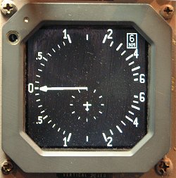 The VERTICAL SPEED instrument with no TCAS information.
The pointer indicates vertical speed in feet per minute.
The VERTICAL SPEED instrument with no TCAS information.
The pointer indicates vertical speed in feet per minute.
The range of TCAS information - the small ring around the aircraft is 2 NM.
The total distance forward is 6 NM and backward 4 NM.
|
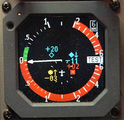 The same instrument during TCAS test.