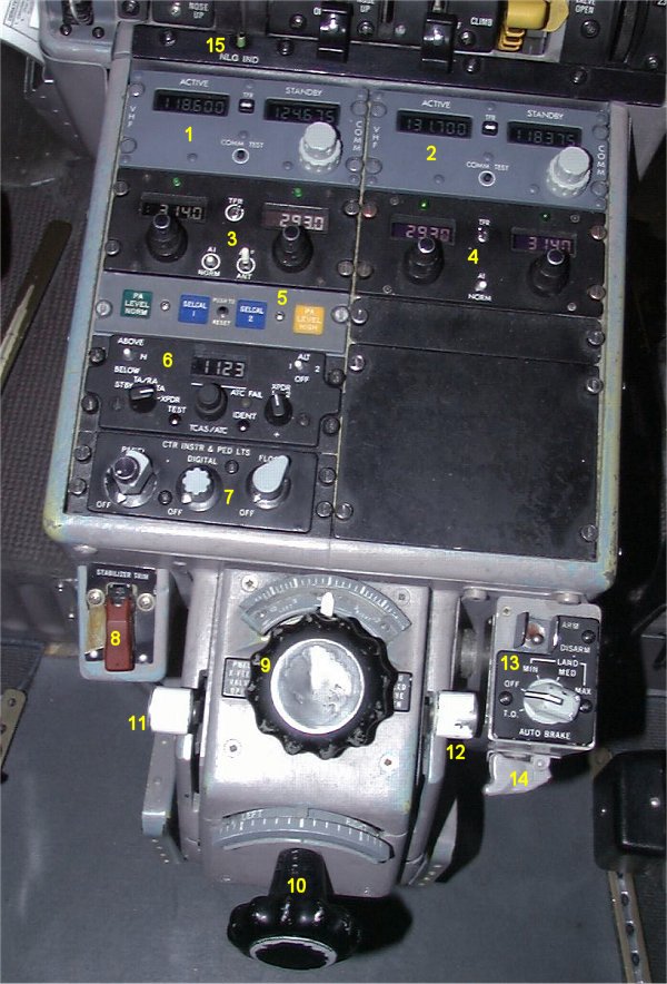
- 1. VHF COM 1.
- The frequency is on the STANDBY (right) side and then transferred to the
ACTIVE (left) side with the TFR button in between.
The COMM TEST button is used to set the squelch to minimum allowing
low level signals to be heard.
- 2. VHF COM 2.
-
- 3. ADF 1.
- The frequency can be set on both sides. The TRF switch is used to
select the active side.
- 4. ADF 2.
-
- 5. SELCAL.
- Also indicator for PA level normal (GREEN) and PA level high (YELLOW).
- 6. TRANSPONDER and TCAS control panel..
- 7. CENTER INSTRUMENT and PEDESTAL LIGHT switches.
- 8. STABILIZER TRIM stop switch.
- An emergency switch, used to prevent stabilizer movements by the
primary trim motor.
- 9. RUDDER TRIM control.
- Rudder trim is set before takeoff to value according to placard on
the L/P panel.
- 10. ALERON TRIM control.
- Aileron trim is set before takeoff to value according to placard on
the L/P panel.
- 11. LEFT PNEUMATIC X-FEED VALVE. OPEN in UP position, CLOSED in down.
- Open to allow pneumatic pressure supply to air condition and
pressurization systems from the left engine.
- 12. RIGHT PNEUMATIC X-FEED VALVE.
- Same as number 11 but from the right engine.
- 13. AUTO BRAKE switch.
-
- 14. HYDRAULIC STOP switch, only found in the simulator.
- Used to stop the hydraulic movements in case of "runaway simulator".
- 15. NOSE GEAR DOWN LOCK indicator.
- This button indicator will appear when the nose gear is fully
extended and nose gear links are locked.
|